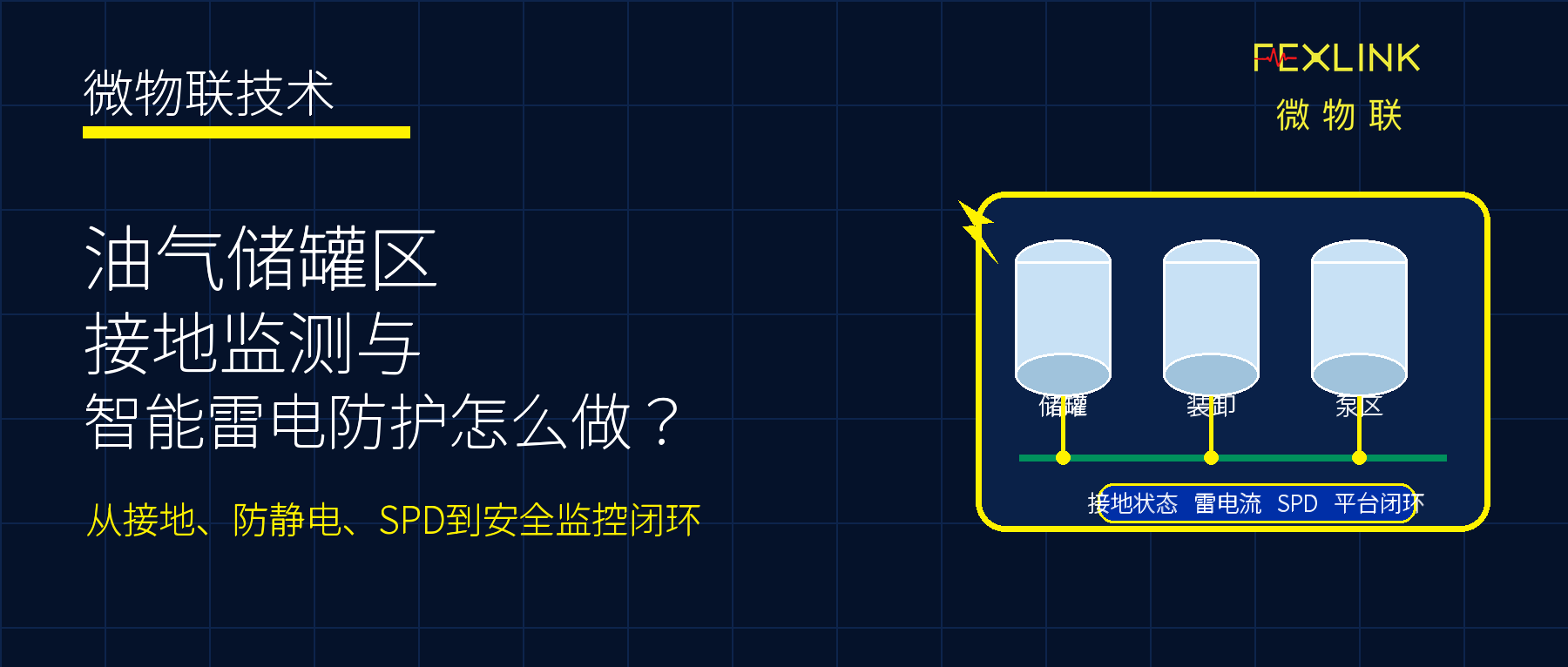
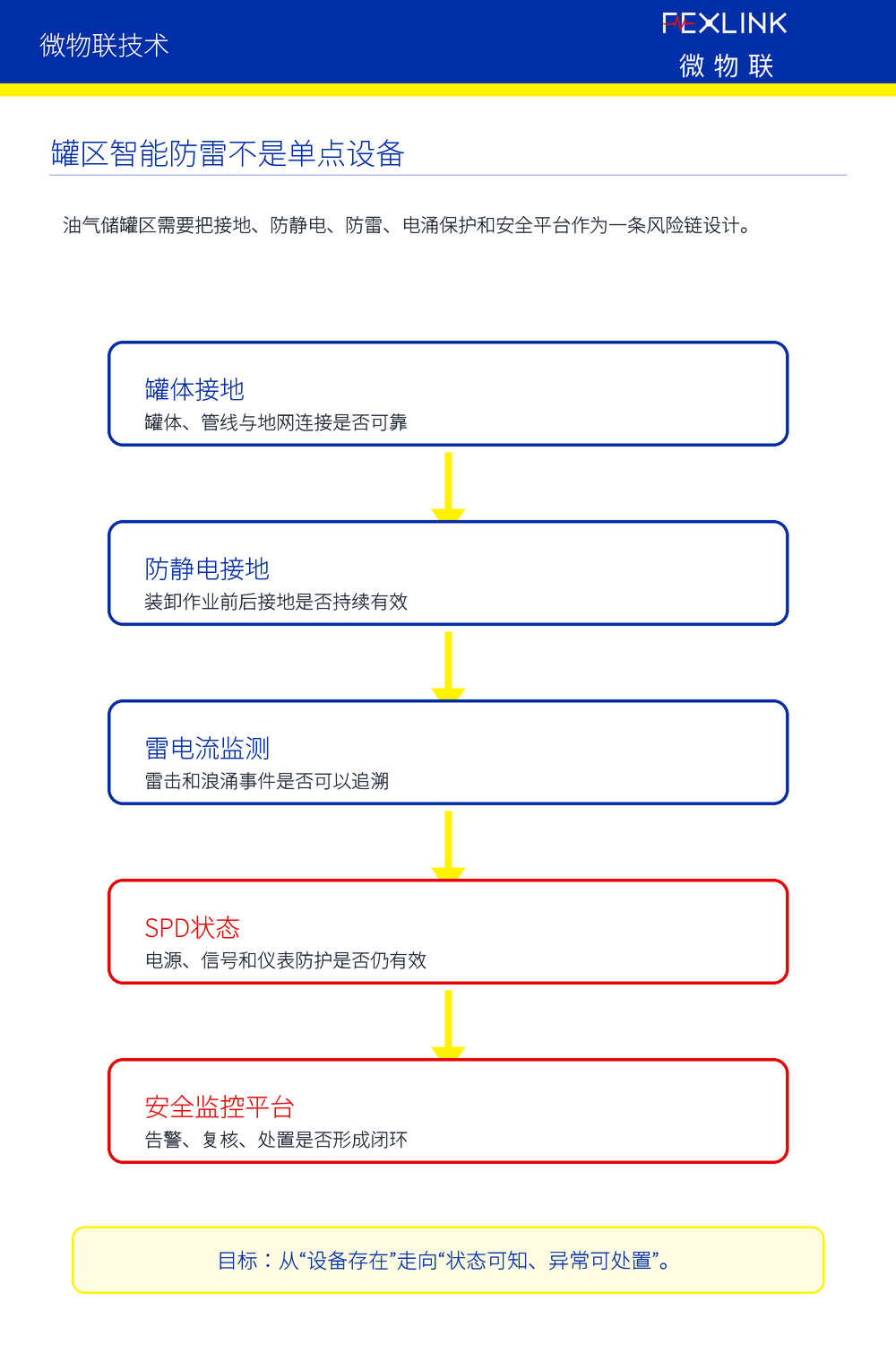
Oil and gas storage tank areas must first identify risk objects. Tank grounding is one of the basic safety paths. It is necessary to pay attention to the main grounding point of the tank, the auxiliary grounding point, the connection between the tank and the ground grid, the equipotential connection between the tank and the pipeline and the platform, and whether the grounding status changes after a thunderstorm.
The loading and unloading area is a key area for anti-static management. The grounding point of the tank car, the loading and unloading arm grounding point, the status of the static grounding clamp, the grounding confirmation before operation, and the grounding maintenance status during operation are all directly related to whether static electricity can be discharged stably. It is best to link this part with the work process. It is not recommended to start work without confirming the grounding. If the work is abnormal, a reminder or interlock prompt should be triggered.
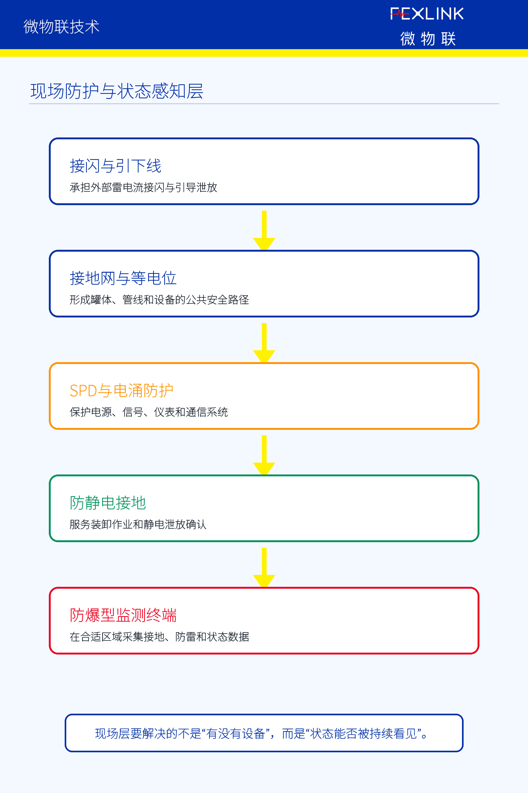
The pump area, process equipment, power distribution cabinets, instrument boxes, DCS/SIS/GDS related instruments, video surveillance and communication equipment also need to be included in lightning protection and grounding status management. For these systems, power lines, signal lines, communication lines and instrument loops may become surge intrusion paths.
2. How should the online monitoring points of ground resistance be arranged?
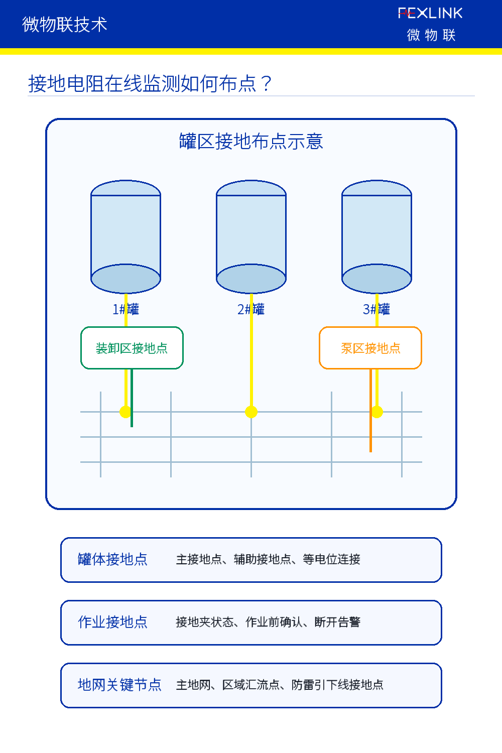
It is not recommended for tank farms to only look at a "total ground value". A more reasonable way is to carry out zoning around the key nodes of the tank, loading and unloading area, pump area, power distribution equipment and ground network. In this way, the platform can determine which tank grounding point has been high for a long time, which point has a sudden change after a thunderstorm, and which area is obviously abnormal compared with similar points.
The tank grounding point should pay attention to the main grounding point, auxiliary grounding point, tank and ground grid connection point, equipotential connection point and lightning protection down conductor grounding point. In the loading and unloading area, attention should be paid to the grounding point of the tank car, the grounding point of the loading and unloading arm, the status of the electrostatic grounding clamp, confirmation before operation and maintenance during operation. In the pump area and power distribution equipment, attention should be paid to the local grounding status of the motor, control cabinet, instrument box, and power distribution cabinet.
The focus of online ground resistance monitoring is not to "display a beautiful value", but to look at long-term trends, abnormal mutations, multi-point comparisons, changes after lightning strikes and correlation with operating status. For large tank farms, these data can better reflect the real risks during the operation phase than a single inspection report.
3. What subsystems should the intelligent lightning protection system include?
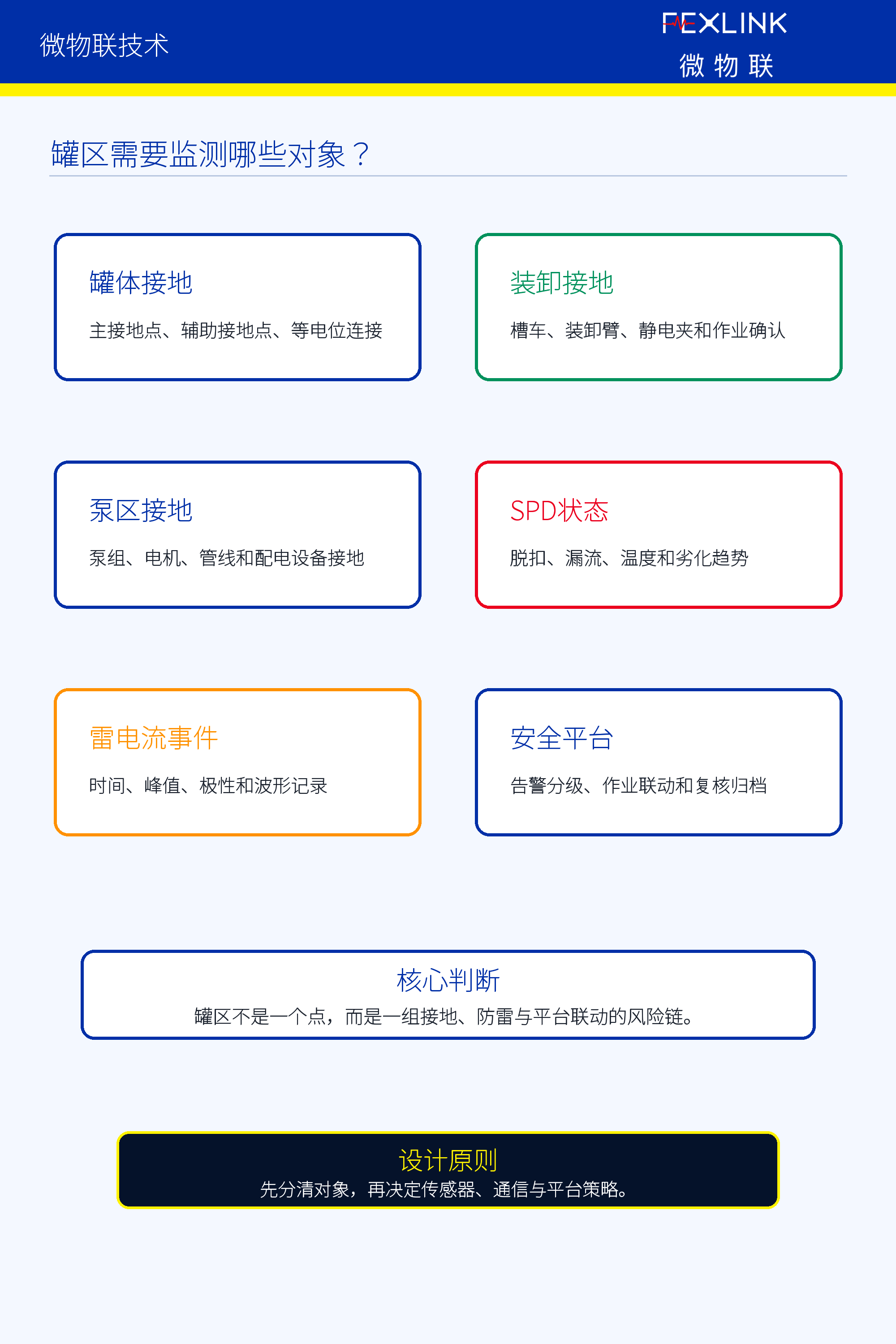
Intelligent lightning protection should not only record whether there is a lightning strike. Lightning current and surge event monitoring should record the occurrence time, event point, peak intensity, polarity, waveform characteristics, duration, impact energy and whether there are multiple impacts as much as possible. These data can provide the basis for accident review, equipment review and risk classification.
SPD and surge protection monitoring cannot only look at tripping remote signals. The instrumentation, communication, video, detection and control systems in the tank area may all be affected by surges, so attention should be paid to SPD tripping, leakage, temperature, degradation trends, backup protection status, action records and life trends.
Anti-static grounding monitoring should cover the loading and unloading operation process, including grounding confirmation before loading and unloading, grounding maintenance during operation, grounding clip contact status, electrostatic discharge path, abnormal disconnection alarm and operation record traces. This data should eventually enter the security monitoring platform instead of being displayed in isolation on a local device.
4. How should the system architecture be done?
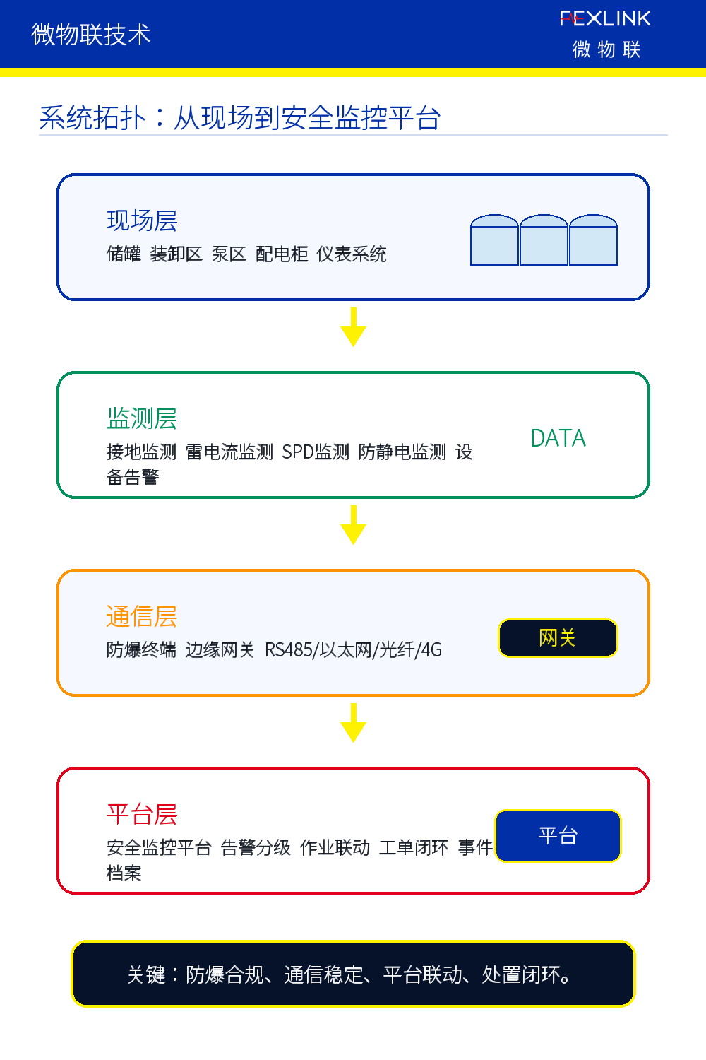
The first layer is the on-site protection layer, including lightning system, down conductor, grounding grid, equipotential bonding, SPD, anti-static grounding and explosion-proof on-site terminal. This layer solves the problems of basic protection and discharge paths, and is the physical base of the system design.
The second layer is the status awareness layer, including ground resistance online monitoring, lightning current monitoring, SPD status monitoring, anti-static grounding monitoring, surge event recording and equipment alarm collection. This layer converts otherwise invisible grounding, lightning protection, anti-static and equipment status into data.
The third layer is the explosion-proof and communication layer. Oil and gas storage tank areas involve explosive hazardous environments. Equipment selection must consider explosion-proof type, temperature group, protection level, power supply method, communication method, anti-corrosion, installation and maintenance, and long-term stability. GB 3836.15-2024 sets out requirements for the design, selection, installation and initial inspection of electrical devices in explosive environments, which means that the relevant equipment must not only look at its function, but also whether it is suitable for on-site hazardous areas and project implementation conditions.
The fourth layer is the platform diagnosis layer, which should support tank area grounding trends, lightning current event files, SPD health status, anti-static grounding status, alarm classification, operation linkage, risk maps and safety reports. The fifth layer is the operation and maintenance closed-loop layer, which needs to realize alarm confirmation, operation reminder, on-site review, maintenance processing, recovery confirmation, event archiving and periodic evaluation.
5. Why must the communication method and explosion-proof selection be explained separately?
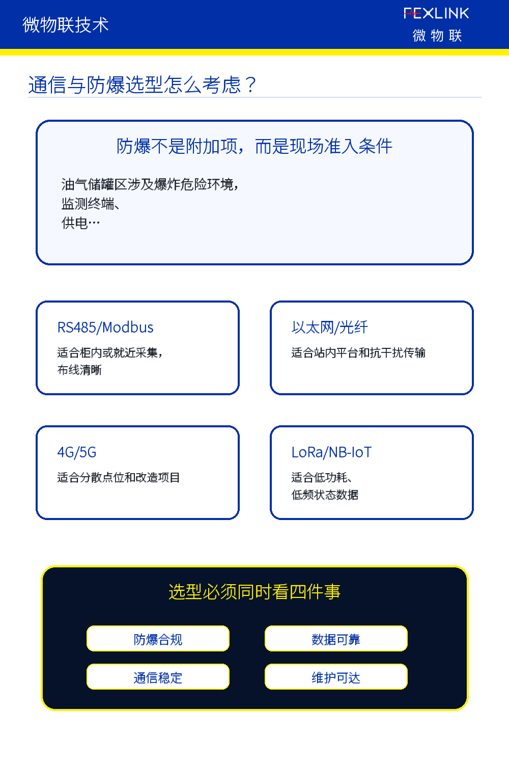
The communication method of the oil and gas storage tank farm cannot only depend on "whether it can be connected to the Internet". RS485/Modbus is suitable for in-cabinet or nearby collection; Ethernet and optical fiber are suitable for in-station platform access and anti-interference transmission; 4G/5G is suitable for dispersed points and renovation projects; LoRa, NB-IoT and other methods are suitable for low power consumption and low frequency status data.
But in petroleum and petrochemical sites, what is more important is whether the communication and power supply solution is suitable for explosion-proof areas, whether it is easy to maintain, whether it is anti-interference, whether it supports breakpoint resume transmission, and whether it can stably enter the safety monitoring system. Explosion-proof compliance is the barrier to entry, and reliable data is the long-term value.
Therefore, explosion-proof terminals, edge gateways, communication links, platform interfaces, and operation and maintenance should be considered together when designing solutions. Just buying a device that can connect to the Internet does not mean building a reliable intelligent lightning protection system.
6. What misunderstandings should be avoided when implementing the system?
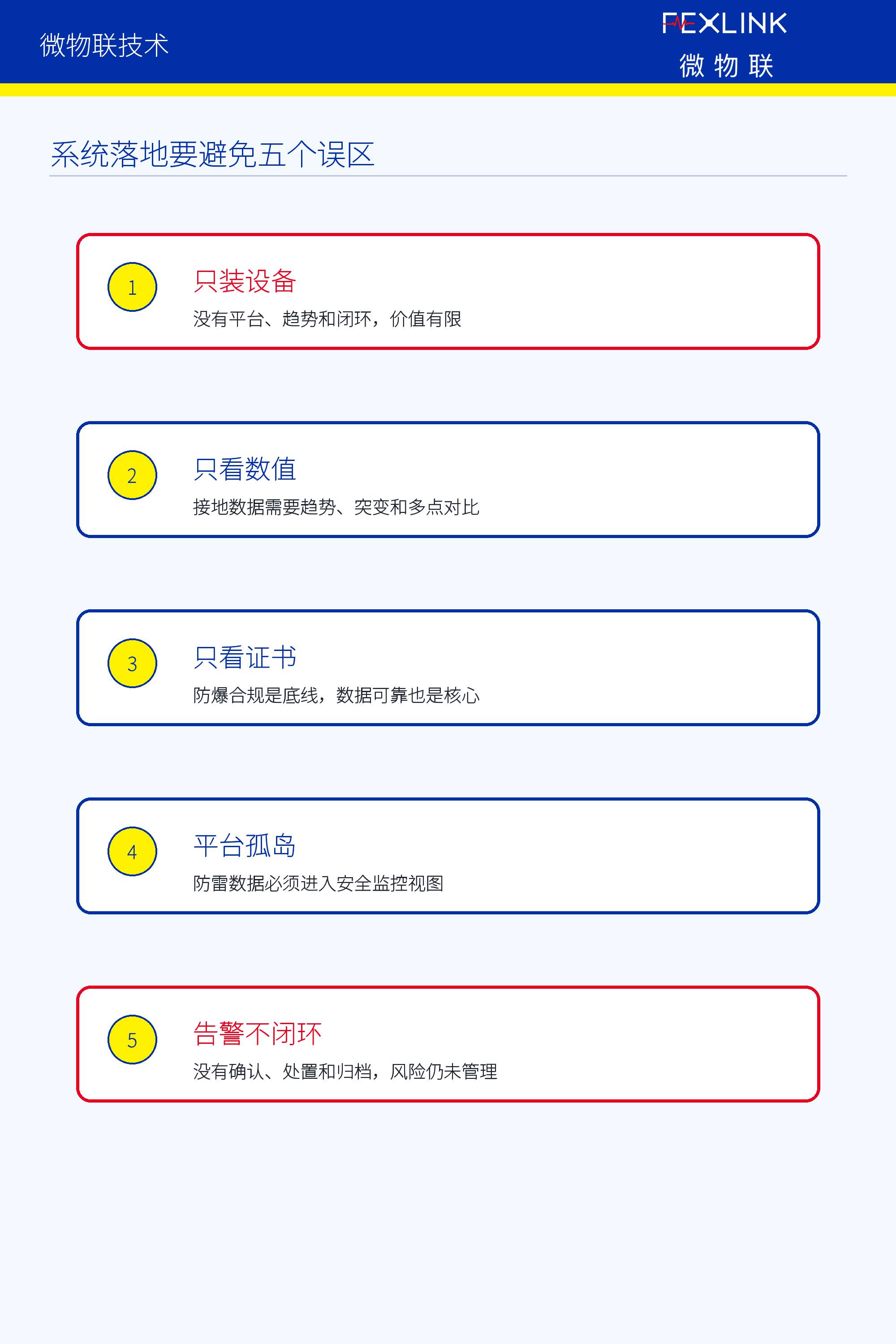
The first misunderstanding is that only the ground resistance monitor is installed without access to the platform. If the ground resistance is only displayed on-site without trends, alarms, records and reviews, the value will be very limited. The second misunderstanding is to only look at the ground resistance and not the anti-static grounding status during loading and unloading operations. The safety of the tank area is not only a ground network problem, but also the electrostatic discharge during the operation is also critical.
The third misunderstanding is to only look at the explosion-proof certificate and not the data reliability. Explosion-proof compliance is the bottom line, but long-term data stability, measurement accuracy, anti-interference ability, and communication reliability are equally important. The fourth misunderstanding is to separate the SPD state and the grounding state, causing the platform to be unable to determine the complete risk chain. The fifth misunderstanding is that there is no closed loop for alarms. If there is no confirmation, review, disposal and archiving after the alarm, the value of the platform will drop significantly.
The real implementation of the system is not to install the equipment once and for all, but to allow data to enter the platform, so that alarms can be classified, so that on-site review can be carried out, and the results can be settled.
7. How does FEXLINK understand the intelligent lightning protection system in oil and gas storage tank areas?
FEXLINK believes that the oil and gas storage tank area ground resistance online monitoring and intelligent lightning protection system cannot be understood as a single equipment purchase, but should be understood as a key data link in the safety monitoring system of major hazard sources.
What the FEXLINK system focuses on is not a single point value, but whether the grounding state is continuously stable, whether electrostatic discharge is reliable, whether lightning current events are traceable, whether SPD is still valid, whether alarms can enter the safety monitoring platform, and whether disposal forms a closed loop.
This system needs to achieve three transformations: from one-time grounding detection to grounding status trend management; from lightning protection equipment configuration to lightning protection system operation monitoring; from single-point alarm to major hazard source safety closed loop.
Conclusion: The core of intelligent lightning protection in tank areas is to let the grounding and lightning protection status enter the safety monitoring system
The online grounding resistance monitoring and intelligent lightning protection system in the oil and gas storage tank area is not to display a few more data, but to integrate grounding, anti-static, lightning protection, surge protection and equipment alarm into a unified risk management process.
For scenarios involving major sources of hazardous chemicals, the real value of the system is not whether the equipment is installed or not, but whether the operating status is continuously known, whether abnormalities are timely alerted, whether disposal forms a closed loop, and whether risks can be identified and managed in advance.
FEXLINK technology will continue to share content related to intelligent lightning protection, early warning of electrical safety, digital power distribution, energy supervision and industrial Internet of Things.
FEXLINK/FEXLINK uses data to reconstruct energy efficiency and electrical safety.
Where there is electricity, there is FEXLINK.
References
National Standard Information Disclosure System: GB 17681-2024 "Technical Specifications for Safety Monitoring of Major Hazardous Sources of Hazardous Chemicals".
Ministry of Emergency Management: "Mandatory National Standard "Technical Specifications for Safety Monitoring of Major Hazardous Sources of Hazardous Chemicals" is released."
National Standard Information Disclosure System: GB 3836.15-2024 "Explosive Environment Part 15: Specifications for Design, Selection and Installation of Electrical Devices".